Los Angeles City Fire Department Requirement
SOLAR PHOTOVOLTAIC SYSTEM
The following are the Los Angeles City Fire Department’s minimum requirement for Solar Photovoltaic System Installations.
Section
1. Reference.
2. Scope.
3. Definitions.
4. Plan Review.
5. Markings, Labels, and Warning Signs.
6. Access, Pathways and Smoke Ventilation.
7. Direct Current (DC) Conductor Locations.
8. Ground Mounted Photovoltaic Arrays.
9. Overhead Arrays on Rooftops (e.g. trellis systems)
10. Photovoltaic Array Diagrams
SEC. 1. REFERENCE.
A. State Fire Marshal
1. Solar Photovoltaic Installation Guidelines.
B. International Fire Code (IFC) – 2006
1. 1003.3.3 – Horizontal projections
2. 1003.6 – Means of egress continuity
3. 1014.3 – Common path of egress travel
C. Los Angeles Municipal Code
1. 57.12.03 – Storage on roofs
2. 57.12.04 – Passageways on roofs
3. 57.138.04- Access aisles and operating clearances
SEC. 2. SCOPE.
This Requirement regulates the installation of solar photovoltaic systems and their ancillary devices. Included are requirements regulating access, fire protection, and other measures and general precautions relating to solar photovoltaic systems.
SEC. 3. DEFINITIONS.
The following words and phrases whenever used in this Requirement shall be construed as defined in this section.
Array – An uninterrupted section of solar photovoltaic panels or a group of interconnected sub-arrays.
Grid – The electrical system that is on the service side of the meter.
Inverter – A device used to convert direct current (DC) electricity from the solar system to alternating current (AC) electricity for use in the building’s electrical system or the grid.
Required access pathway – A required walking pathway that is designed to provide emergency access, meeting the requirements in Sections 57.46.06 and 57.46.09.
Solar photovoltaic systems – A system of component parts that receives sunlight and converts it to electricity.
Sub-array – Uninterrupted sections of solar photovoltaic panels interconnected into an array.
Travel distance – The walking distance between two points.
Venting cutout – Section(s) in an array that are designed to accommodate emergency ventilation procedures.
SEC. 4. PLAN REVIEW.
All solar installations on buildings shall be approved by the Construction Services Unit prior to installation. At a minimum the following information shall be presented for approval: A Site plan (to scale) of the structure, on which the photovoltaic array are to be installed, showing the following:
1. Footprint of the building and north reference point.
2. Location of all structures on site.
3. Street address of building.
4. Access from street to building.
5. Location of arrays.
6. Location of disconnects.
7. Location of required signage.
8. Location of required access pathways.
B. Plan and elevation views of building clearly showing the following:
1. Array placement.
2. Roof ridgelines.
3. Eave lines.
4. Equipment on roof.
5. Other objects that may be present on the roof; such as, vent lines,
skylights, and roof hatches.
C. Location and verbiage of all markings, labels, and warning signs.
D. Building photographs that may be useful in the evaluation of the array placement.
SEC. 5. MARKINGS, LABELS, AND WARNING SIGNS.
A. Purpose: Provides emergency responders with appropriate warning and guidance with respect to isolating the solar electrical system. This can facilitate identifying energized electrical lines that connect the solar panels
to the inverter, as these should not be cut when venting for smoke removal.
B. Main Service Disconnect:
1. Residential buildings – the marking may be placed within the main service disconnect. The marking shall be placed on the outside cover if the main service disconnect is operable with the service panel closed.
2. Commercial buildings – the marking shall be placed adjacent to the main service disconnect clearly visible from the location where the lever is operated.
3. Markings: Verbiage, Format, and Type of Material.
a. Verbiage: CAUTION: SOLAR ELECTRIC SYSTEM CONNECTED
b. Format:
(1) White lettering on a red background.
(2) Minimum 3/8 inches letter height.
(3) All letters shall be capitalized.
(4) Arial or similar font, non-bold.
c. Material:
(1) Reflective, weather resistant material suitable for the environment (use UL – 969 as standard for weather rating). Durable adhesive materials meet this requirement.
C. Marking Requirements on DC Conduit, Raceways, Enclosures, Cable Assemblies, DC Combiners, and Junction Boxes:
1. Markings: Placement, Verbiage, Format, and Type of Material.
a. Placement: Markings shall be placed every 10 feet on all interior and exterior DC conduits, raceways, enclosures, and cable assemblies, at turns, above and /or below penetrations, all DC combiners, and junction boxes.
b. Verbiage: CAUTION: SOLAR CIRCUIT
Note: The Format and Type of Material shall adhere to “V. B-3b, c” of this Requirement.
D. Inverters – Are Not Required to Have Caution Markings.
SEC. 6. ACCESS PATHWAYS AND SMOKE VENTILATION.
A. Solar Photovoltaic Systems for One and Two Family Dwelling Units: All plans are required to be reviewed by the Fire Department.
1. Access:
a. Buildings with a hip roof layout
(1) Panels shall be located in a manner that provides one three-foot wide clear access pathway from the eave to the ridge on each roof slope where panels are located.
(2) The access pathway shall be located at a structurally strong location on the building (i.e. bearing wall).
b. Buildings with a single ridge:b. Buildings with a single ridge:
(1) Panels shall be located in a manner that provides two three-foot wide access pathways from the eave to the ridge on each slope where panels are located.
(2) Access pathway clear width shall not include any eaves overhang.
d. Dead ends:
(1) Where there are two or more access pathways the clear pathways shall be arranged so there are no dead ends greater than 25 feet in length.
(2) If any access pathway leading to a dead end is greater than 25 feet in distance it shall continue on to the next access pathway.
(3) At no time shall any access pathway cause a person’s travel distance to exceed 150 feet before arriving at another required access pathway.
2. Ventilation:
a. An uninterrupted section of photovoltaic panels (array) shall not exceed 150 feet by 150 feet in dimension in either axis.
b. Panels shall be located no higher than three feet below the ridge.
EXCEPTION: The panels may be located two feet below the ridge if the Department has determined that an approved product or method will provide an equal or greater opportunity for ventilation.
B. Commercial Buildings and Residential Housing Comprised of Three or More Units:
EXCEPTION: The Department may determine that the roof configuration is similar to residential (such as in the case of townhouses, condominiums or single family attached buildings), and apply the one and two family
residential unit access and ventilation requirements.
1. Access:
a. A minimum six-foot wide clear perimeter is required around the edges of the roof.
EXCEPTION: If either axis of the building is 250 feet or less, there shall be a minimum four feet wide clear perimeter around the edges of the roof.
2. Pathways: Shall be established in the design of the solar installation and meet the following requirements:
a. Located over structurally supported members.
b. Center line axis pathways shall be provided in both axis of the roof. Centerline axis pathways shall run on structurally supported members or over the next closest structurally supported member nearest to the centerlines of the roof.
c. A minimum of four feet clear straight-line pathway shall be provided from the access path to skylights and/or ventilation hatches.
d. A minimum of four feet clear straight-line pathway shall be provided from the access to roof standpipes.
e. Not less than a four feet clear around roof access hatches with a minimum of one pathway that is straight and not less than four feet clear to the parapet or roof edge.
3. Ventilation:
a. Arrays shall be no greater than 150 feet by 150 feet in dimension in either axis.
b. Ventilation options between array sections shall be one of the following:
(1) An access pathway eight feet or greater in width.
(2) The access pathways shall be four feet or greater in width and bordering on the existing roof skylights or ventilation hatches.
(3) The access pathways shall be four feet or greater in width with bordering 4 feet by 8 feet “venting cutouts” every 20 feet on alternating sides of the pathway.
SEC. 7. DIRECT CURRENT (DC) CONDUCTOR LOCATIONS.
A. Conduit, wiring systems, and raceways:
1. Located as close as possible to the ridge, hip or valley and from the hip or valley as directly as possible to an outside wall.
B. Conduit runs between sub arrays and DC combiner boxes shall:
1. Use design guidelines that minimizes the total amount of conduit used on the roof by taking the shortest path from the array to the DC combiner box.
2. The DC combiner boxes are to be located such that conduit runs are minimized in the pathways between arrays.
C. DC wiring:
1. DC wiring shall be run in metallic conduit or raceways when located within enclosed spaces in a building.
2. When possible DC wiring shall run along the bottom of load bearing members.
SEC. 8. GROUND MOUNTED
A. Setback Requirements:
1. Does not apply to ground mounted freestanding photovoltaic arrays.
2. A 10 feet minimum clearance is required around ground-mounted photovoltaic systems.
3. Shall not obstruct Fire Department access.
SEC. 9. OVERHEAD ARRAYS ON ROOFTOPS (e.g. trellis systems).
A. Minimum Requirements:
1. Overhead arrays shall comply with the same marking, labeling, and warning signs as required of roof-mounted systems.
2. There shall be an unobstructed clearance of seven feet or more between the roof deck surface and the underside of the overhead array.
3. The regulations in 57.12.03, and 57.138.04 of the Los Angeles Fire Code shall be complied with.
4. An uninterrupted section of solar photovoltaic panels shall not exceed 150 feet by 150 feet in dimension in either axis.
5. The overhead clear width between arrays or sub-arrays shall be four feet or greater extending from the edge of the array(s) to the roof deck surface, thereby, maintaining an unobstructed access pathway, and providing for emergency ventilation procedures.
6. The use of the area below arrays is prohibited.
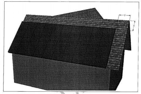
Diagram 1: Cross Gable Roof
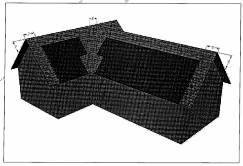
Diagram 2: Cross Gable With Valley
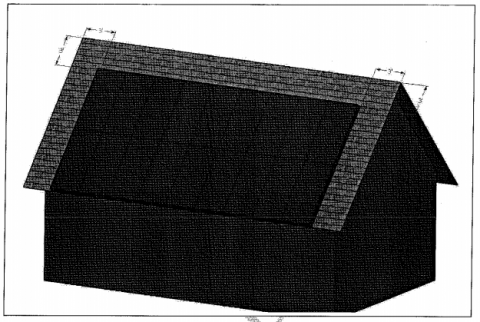
Diagram 3: Full Gable
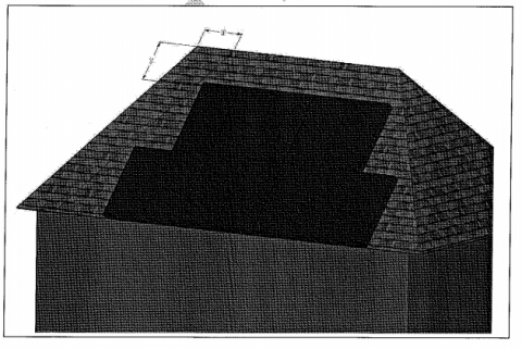
Diagram 4: Full Hip Roof
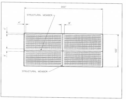
Diagram 5: Solar Arrays for Large Commercial (8 Foot Walkways)
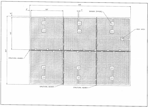
Diagram 6: Solar Arrays for Large Commercial (4 Foot Walkways with 8' X 4' venting Opportunities every 20 Feet)
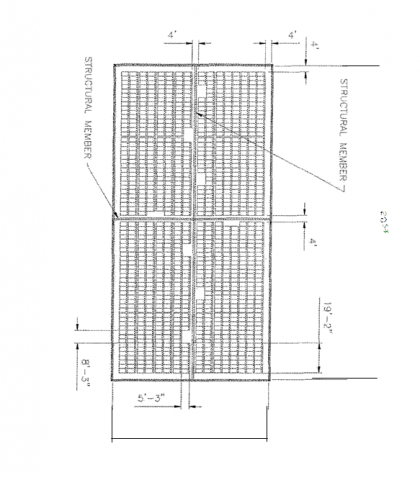
Diagram 7: Solar Arrays for Small Commercial (4' Walkways with 8' x 4' Venting Opportunities every 20' along Walkways)
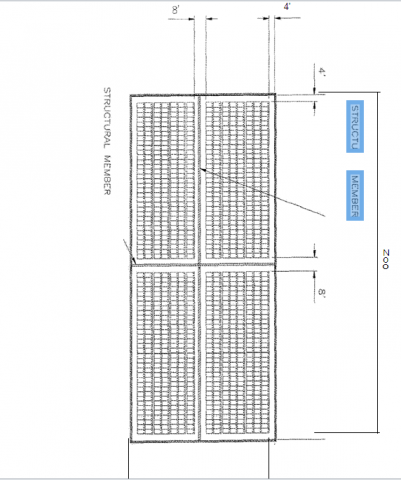
Diagram 8: Solar Arrays for Small Commerical (8' Walkways)
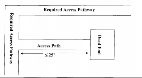
Diagram 9: Travel distance for access pathway leading to a dead end shall not exceed 25 feet.
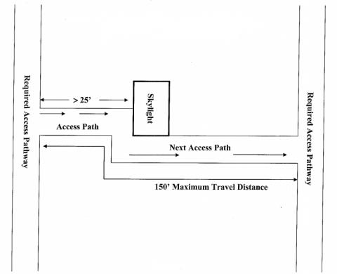
Diagram 10: Travel distance for access pathway exceeding 25 feet shall require a second access pathway. Access pathways shall have a maximum 150 feet travel distance.
